Digital vs. Analog in Electronics: Digital electronic information is discrete numbers or bits. An analog signal is a continuous signal. An ADC (Analog to Digital Converter) converts a continuous signal, for instance a microphone signal, to discrete numbers that a computer can understand. That's the best I can explain on the spot. Dan and Tom say (I'm paraphrasing) that if you're asking yes or no, it's digital, if you're asking "how much" it's analog.
So, we're working with digital signals, which means we're going to tell whether something is on or off. Switches are good for this. It'll give us a taste of how to deal with inputs to the PIC, since we've already done digital output
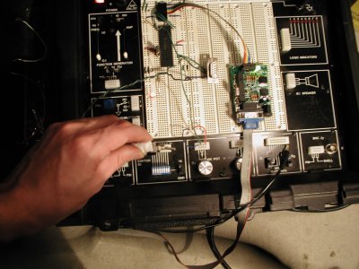
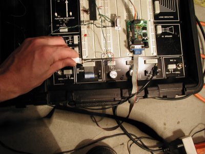
Wiring for this section is easy. We'll take a toggle switch, of which there are many varieties, attach the power to your board's +5V, and the other end to a port pin on the PIC. The electricity will flow from +5V to one pole of your switch, which will either let it through or stop it. Then, if the switch is open, it will flow to your PIC. The PIC basically is in a loop that says "Is there current on that pin? Yes? Do this. No? Do this." It's that easy.
I never actually did this in asm, I did it in JAL, so the code below is untested. It's simple code though, so if this doesn't work I'm sure you'll figure it out (if it is wrong let me know and I'll actually get it right. God I'm lazy. It probably has more to do with lots of work at the end of term right now. Anyway, moving on).
Start as usual with your beautiful header. I won't repeat it right here, but I'll include it in the final for completeness. The program is going to be a simple variation on your LED blinker. That is, each loop it will check the switch and turn the LED on or off correspondingly. You could just attach the LED to the switch, but this way makes it easy to add features like, you need to flip the switch three times before the LED goes on. I'll leave such innovations to you.
The first thing after your org statement should be setting up the ports for i/o. Recall from the LED Chaser that clearing a bit in a TRIS register sets the corresponding pin to output. In the LED Chaser we set the whole port to output, but here I'm assuming your LED is on RD1, and your switch is on RD2, so you can't set the whole D TRIS, you need to set each bit so that RD1 is output and RD2 is input. This could be done with a bit set and bit clear instruction like this:
    org 0x0000

    bcf TRISD, RD1 ; set pin D1 to output
    bsf TRISD, RD2 ; set pin D2 to output
A more elegant (I think) way to do this would be soemthing like this:
    org 0x0000

    movlw B'00100000' ; set only pin 2 to input (numbering starts at 0)
    movwf TRISD
I think this is better for two reasons. First, it lets you see the port setting right there, I think it's more readable than a bunch of bsf and bcf statements. Second, you can set all the pins with two instructions. Since we're only setting two pins there's no savings, but if you're setting more pins it can save a lot of time.
Next, open your main loop with the label "Main". This loop will simply have a conditional that checks the value of PORTD, RD2 (where the switch is) to see if it's 1, if it is, it turns on the light, otherwise it turns it off.
Main
    btfss PORTD, RD2 ; check RD2 bit is set, skip next line if yes.
    bcf   PORTD, RD1 ; turn off the LED
    bsf	  PORTD, RD1 ; turn on the LED
    goto Main        ; loop
It's that easy. The hardest part for me was getting the wiring on the switch. I had just taped it for testing, and I kept thinking my program wasn't working, but then realized that sometimes the contacts were touching, sometimes not. It may be best to solder the wires to the switch just to eliminate the possibilities. Here's the final code:
;;;;;;;;;;;;;;;;;;;;;;;;;;;;;;;;;;;;;;;;;;;;;;;;;;;;;;;;;;;;;;;;;;;;;
;; digital_io.asm: Basic digital in/out for a PIC 18F452
;;
;; By Ian Smith-Heisters ian{remove this}\at 0x09{remove this}.com
;;   12-07-2004: Started
;;   12-07-2004: version 1
;;;;;;;;;;;;;;;;;;;;;;;;;;;;;;;;;;;;;;;;;;;;;;;;;;;;;;;;;;;;;;;;;;;;;

    title "Get your digital on"
    List p=18f452,f=inhx32
    #include <p18f452.inc>

    __CONFIG    _CONFIG1H, _OSCS_ON_1H & _XT_OSC_1H ; External Clock on OSC1 & OSC2
    __CONFIG    _CONFIG2L, _BOR_ON_2L & _BORV_20_2L & _PWRT_OFF_2L ; Brown out reset on at 2.0V, no power-up timer
    __CONFIG    _CONFIG2H, _WDT_OFF_2H & _WDTPS_128_2H ; watchdog off, postscaler count to 128
    __CONFIG    _CONFIG3H, _CCP2MX_ON_3H ; CCP2 pin Mux enabled. What is this?
    __CONFIG    _CONFIG4L, _STVR_ON_4L & _LVP_ON_4L & _DEBUG_OFF_4L ; Stack under/overflow reset on, LVP on, debug off
    __CONFIG    _CONFIG5L, _CP0_OFF_5L & _CP1_OFF_5L & _CP2_OFF_5L & _CP3_OFF_5L ; all protection off
    __CONFIG    _CONFIG5H, _CPB_OFF_5H & _CPD_OFF_5H
    __CONFIG    _CONFIG6L, _WRT0_OFF_6L & _WRT1_OFF_6L & _WRT2_OFF_6L & _WRT3_OFF_6L
    __CONFIG    _CONFIG6H, _WRTC_OFF_6H & _WRTB_OFF_6H & _WRTD_OFF_6H
    __CONFIG    _CONFIG7L, _EBTR0_OFF_7L & _EBTR1_OFF_7L & _EBTR2_OFF_7L & _EBTR3_OFF_7L
    __CONFIG    _CONFIG7H, _EBTRB_OFF_7H

    org 0x0000

    movlw B'00100000' ; set only pin 2 to input (numbering starts at 0)
    movwf TRISD

Main
    btfss PORTD, RD2 ; check RD2 bit is set, skip next line if yes.
    bcf   PORTD, RD1 ; turn off the LED
    bsf	  PORTD, RD1 ; turn on the LED
    goto Main        ; loop

    end
off
on