There is an excellent tutorial here that I HIGHLY recommend going through. It will teach you how to do serial io with bit banging, which will give you a good background of how RS-232 (the serial protocol) works. At least read it. The code itself doesn't work straight out of the box on the PIC 18F452. There's one instruction I had to change, if I recall correctly, change every occurence of rrf to rrcf. It's just a change in PIC instruction names between generations.
Briefly, RS-232 sends bits with one start bit and one stop bit at +12V and -12V. It uses inverted logic, meaning the voltage goes low for a 1 and high for a 0. (a better explanation of RS-232 here) This is a problem if you're trying to go straight between the computer and the PIC (I'll get to the alternative later). The PIC is built to output using TTL, which is similar, but uses normal logic (not inverted) and goes between 0V and +5V. Luckily, the computer can read TTL. Unluckily, the computer will try to talk back in RS-232, and the 12V will fry your PIC if it's not insulated by a resistor. See Physical Computing or do a google to get the rating for the resistor you need between the computer's TX (shorthand for transfer) and the PIC's RX (receive). I can't remember it off the top of my head.
So, to get the PIC to talk to the computer directly using the scheme in the tutorial above, all you need to do is insulate the PIC's RX with a resistor and invert all the logic. To invert the logic change all the bsf's to bcf's and vice versa in the XMIT and RCV subroutines.
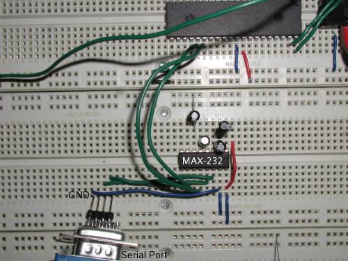
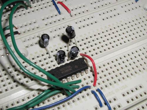
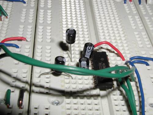
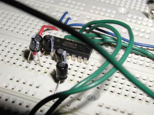
This is the easy way to do serial communication with the PIC. It requires a MAX232, which is an integrated circuit that is available everywhere worthwhile for less than a dollar. It was very difficult for me to figure out how to wire it, so here's a bunch of pictures:
Overview
A bunch from the sides
The code I will show you here just does output from the PIC. I haven't needed input yet, so I haven't done it. It shouldn't be hard to add to this. This code will send the alphabet to the computer from the PIC.
Let's start with our LED Chaser and build on that skeleton. I did this so that the LED will keep blinking while we're working. This is helpful at this stage to debug and be sure the PIC is getting through its loop. It's also useful because you want to pause between sending each letter, otherwise they flood in at several hundred a second. The LED delays work nicely for that.
; Define Constants
COUNT1	equ	0x00
COUNT2	equ	0x01

;;Subroutines
Main
		bsf	PORTD,RD1	; turn off the LED
		call	Delay		; wait

		bcf	PORTD,RD1	; turn off the LED
		call	Delay		; wait
		goto	Main

Delay
		setf	COUNT1
		setf	COUNT2
Loop1
                decfsz	COUNT1, F
		goto	Loop1
		setf	COUNT1
		decfsz	COUNT2, F
		goto	Loop1
		return
I think that's basically the LED Chaser, with the headers removed of course. See below for that.
We need to add one variable that will hold the letter we are sending to the computer:
char equ 0x04
As for port setup, we're just blinking the LED, so setting port D all out will do:
clrf TRISD
Most of the rest of what we're going to do is by use of subroutines, so start adding subroutines below the Delay sub.
The first sub is very simple, it just sets char to the ASCII leter 'A'. We'll do this a lot, so we'll make it a sub to save memory.
Reset_char
                movlw   'A'
		movwf	char
		return
Before we go on, let's just add a line before the Main loop, and after the port setup that will initialize char to 'A'. Just call the Reset_char sub for this.
Next we need two more subroutines, one to initialize the Universal Asynchronous Receiver Transmitter, or UART. The UART controls the RX and TX pins to send the RS-232 signal.
Initializing the UART has 5 steps. There are more advanced features too, but these work. For more information look at the datasheet at p. 174
The Transmit Status and Control Register (TXSTA) lets you setup how the TX works, and also allows you to later check the status of the transmission. The TXSTA has 8 bits (see datasheet p. 168 for more info):
		movlw	B'00100110'	; See datasheet p 168
		movwf	TXSTA
I'll gloss over the setting for the same register on the receive side. Suffice to say you need to set the first bit to enable the serial port.
		movlw	B'10000000'	; Turn serial port on.
		movwf	RCSTA
Now we set the baudrate. To do this we use the Baudrate Generator. You feed the baudrate generator a decimal number (gotten from the tables in the datasheet on pp. 171-173) and it sets the baudrate for you. What the baudrate is is determined by whether you set the high speed baudrate bit of TXSTA, which we did to gain accuracy. If you look on the tables on p. 171 of the DS you'll notice that there's a % error column. We want to get a 9600 baud, with the smallest margin of error. This means we set the high speed bit and give the baudrate generator (SPBRG) the decimal number 25
		movlw	D'25'		; Set baud rate to 9600 w/ 4 MHz clock. +.16% error
		movwf	SPBRG
Now we set the TX pin to output, just like we set the pins to output previously
bcf TRISC, TX ; Set TX to output
The last step of UART initialization is to clear the transmit interrupt. This would make it so when the PIC receives something it can branch from the current routine to deal with the transmission. We're not using this, but it's good to clear it nonetheless
bcf PIE1, TXIE ; clear transmit interrupt
Put all this together into a subroutine call UART_Init, and it should look like this:
UART_Init
		movlw	B'00100110'	; See datasheet p 168
		movwf	TXSTA
		movlw	B'10000000'	; Turn serial port on.
		movwf	RCSTA
		movlw	D'25'		; Set baud rate to 9600 w/ 4 MHz clock. +.16% error
		movwf	SPBRG

		bcf	TRISC, TX	; Set TX to output
		bcf	PIE1, TXIE	; clear transmit interrupt

		return
Actually transmitting over the UART is easy. Basically you just move your number to the TXREG and the PIC sends it for you while the PIC can go on and do other things. The only catch is that you want to make sure the PIC has sent the previous byte, so you put a loop before the transmission to wait until the last one is done (if it isn't already). Note that this implementation assumes the byte to be transferred is in the the WREG.
UART_Put
		btfss 	PIR1, TXIF	; Wait for TXREG to be empty
		goto	UART_Put
		movwf 	TXREG		; Transmit byte in W
		return
Now you've got all the subs you need. Put them after your main loop (or the PIC will run through them before it gets to Main) and call the UART_Init just before the Main loop, and after you set char.
Now we need to actually do the transfer. To go through the alphabet all we do is add one to our letter 'A'. If it's larger than 'z' (z is represented by a higher number than A in ASCII, 122 and 65 respectively) we reset back to 'A'.
Main
		bsf	PORTD,RD1	; turn off the LED
		call	Delay		; wait

		;; This is the transmission
		movf	char, W
		call	UART_Put
		incf	char, F		; increment char
		movlw	'z'     	; reset char if greater than z
		cpfslt	char
		call    Reset_char

		bcf	PORTD,RD1	; turn off the LED
		call	Delay		; wait
		goto	Main
Schlack the whole thing together and you get the following. If you don't get it or I'm moving too fast, email me.
;;;;;;;;;;;;;;;;;;;;;;;;;;;;;;;;;;;;;;;;;;;;;;;;;;;;;;;;;;;;;;;;;
; rs232_test-1.asm
;	blinks and LED while sending the alphabet to a com port using RS-232
;	by Ian Smith-Heisters, v.1 complete on October 14th, 2004
;;;;;;;;;;;;;;;;;;;;;;;;;;;;;;;;;;;;;;;;;;;;;;;;;;;;;;;;;;;;;;;;;

	title "RS232 with built in TX"
	List p=18f452,f=inhx32
	#include <p18f452.inc>

;The config aliases are already defined in the 18f452 header file.
	__CONFIG    _CONFIG1H, _OSCS_ON_1H & _XT_OSC_1H ; External Clock on OSC1 & OSC2
	__CONFIG    _CONFIG2L, _BOR_ON_2L & _BORV_20_2L & _PWRT_OFF_2L ; Brown out reset on at 2.0V, no power-up timer
	__CONFIG    _CONFIG2H, _WDT_OFF_2H & _WDTPS_128_2H ; watchdog off, postscaler count to 128
	__CONFIG    _CONFIG3H, _CCP2MX_ON_3H ; CCP2 pin Mux enabled. What is this?
	__CONFIG    _CONFIG4L, _STVR_ON_4L & _LVP_ON_4L & _DEBUG_OFF_4L ; Stack under/overflow reset on, LVP on, debug off
	__CONFIG    _CONFIG5L, _CP0_OFF_5L & _CP1_OFF_5L & _CP2_OFF_5L & _CP3_OFF_5L ; all protection off
	__CONFIG    _CONFIG5H, _CPB_OFF_5H & _CPD_OFF_5H
	__CONFIG    _CONFIG6L, _WRT0_OFF_6L & _WRT1_OFF_6L & _WRT2_OFF_6L & _WRT3_OFF_6L
	__CONFIG    _CONFIG6H, _WRTC_OFF_6H & _WRTB_OFF_6H & _WRTD_OFF_6H
	__CONFIG    _CONFIG7L, _EBTR0_OFF_7L & _EBTR1_OFF_7L & _EBTR2_OFF_7L & _EBTR3_OFF_7L
	__CONFIG    _CONFIG7H, _EBTRB_OFF_7H

	org	0x0000

; Define Constants
COUNT1	equ	0x00
COUNT2	equ	0x01

; Define variables
char	equ 0x04

; Set port D to all output
	clrf	TRISD

; initialize variables
        call    Reset_char              ; sets char to 'A'

	call	UART_Init
Main
		bsf	PORTD,RD1	; turn off the LED
		call	Delay		; wait

		movf	char, W
		call	UART_Put
		incf	char, F		; increment char
		movlw	'z'     	; reset char if greater than z
		cpfslt	char
		call    Reset_char

		bcf	PORTD,RD1	; turn off the LED
		call	Delay		; wait
		goto	Main

;; Subroutines
Reset_char
                movlw   'A'
		movwf	char
		return

Delay
		setf	COUNT1
		setf	COUNT2
Loop1
                decfsz	COUNT1, F
		goto	Loop1
		setf	COUNT1
		decfsz	COUNT2, F
		goto	Loop1
		return

UART_Init
		movlw	B'00100110'	; See datasheet p 168
		movwf	TXSTA
		movlw	B'10000000'	; Turn serial port on.
		movwf	RCSTA
		movlw	D'25'		; Set baud rate to 9600 w/ 4 MHz clock. +.16% error
		movwf	SPBRG

		bcf	TRISC, TX	; Set TX to output
		bcf	PIE1, TXIE	; clear transmit interrupt

		return

UART_Put
		btfss 	PIR1, TXIF	; Wait for TXREG to be empty
		goto	UART_Put
		movwf 	TXREG		; Transmit byte in W
		return

	end