This tutorial gets your PIC in the breadboard, connects its clock crystal, gets power to it, and hooks it up for ICSP. The pictures may be a bit confusing because I did this in two stages. What I'm going to tell you how to do is combine the two steps, so you'll end up with the power source from the first and the programming hookup from the second. You'll see.
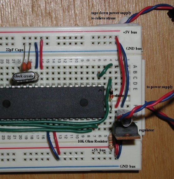
Take your PIC and plug it into your bread board so it straddles the gap in the middle of the board. Put it 15-20 rows down from the top so you have room for your programmer connection and power regulator.
These would be exactly the instructions from O'Sullivan and Igoe's Physical Computing so I won't repeat them in too much detail. This is very standard, and easy to follow instructions are all over the web, including in the datasheet. Follow their instructions to solder the power plug to two wires, which in turn go on a two prong header, which is glued and taped for insulation.
Put the power regulator on the top three rows of the breadboard with the input on the top row. Put the power connector's power to the regulator's input, and the connector's ground to the regulator's ground. Run wires from the regulator's ground to each ground bus on the breadboard. Run wires from the regulator's +5V output to the breadboard's power busses.
Connect the PIC's MCLR to +5V via a 10K Ohm resistor and a switching diode like this (yes, ASCII schematics. If this isn't good enough for you, look here) [begin ASCII diagram] +5V -> 10K Ohm Resistor -> Switching Diode -> MCLR [end ASCII diagram].
Connect the GND and +5V on each side of the PIC to the ground and power busses respectively.
Anchor the wires running to the power supply by taping them to the bottom of the breadboard in order to relieve stress.
It should look something like this, but with more room between the power regultor and the PIC so that we can put the programmer connection in there. Ignore the green wires running from the left. They're from the programmer, but we'll be doing it differently.
Put one pin of the clock crystal in CLKIN and the other in CLKOUT. Each pin is identical, so it there's no wrong way to connect them. Connect both clock pins to ground via 22pF capacitors.
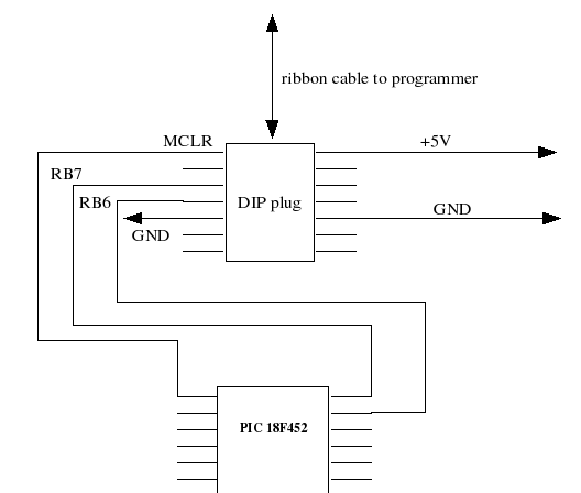
Cut a length of 10 conductor ribbon cable. It will connect your programmer to your board, so cut however much is convenient. Take your IDC socket and clamp it onto one end of the cable. Take the DIP plug and clamp it onto the other end. Take a multimeter and check for continuity between the pins on the plug and the holes on the socket.
Plug the DIP plug into your breadboard between the power supply and the PIC so that it straddles the gap in the middle of the breadboard (what's the technical name for that thing?). Use wires to connect the pins as shown in the pictures below.
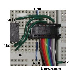
Test all the connections. Take the ICP socket (on the other end of the cable running to the DIP plug) and connecting it to the programmer's headers. Make sure you have it one right, so that there's continuity from header 1 on the programmer to MCLR on the board. To do this, plug it all together. Turn the programmer over. Touch one multimeter probe to the solder on the bottom of the programmer on pin 1, it should say 1 next to it. Put the other multimeter probe on the breadboard's MCLR and check for continuity. If that's okay, then everything is plugged together correctly
Plug the programmer into your computer. Plug in the breadboard's power adapter. Plug in the programmer's adapter. Start the MELabs programmer interface thingy. Select 18F452 from the drop down list. Run a test, I think it's called check version or something. If the program responds that it can't find the PIC or the version is invalid there's a bad connection somewhere.