Handheld web server
links
In this tutorial I will design and manufacture an open source, handheld, battery powered web server.
Initial brainstorming of possible microcontroller to use (in no particular order):
Feb 5
Decided on using
sanguino (
google code repo), which is a couple extra bootloaders for the Arduino environment to support the ATmega644, ATmega644P and the ATmega1284P. I'll probably use the
ATmega1284P, as it has 128kB of flash memory, which should be plenty to fit libraries for a display, SD card, wify radio and then some.
We looked at this
D1339 3.3V realtime clock, thinking about whether something like that is needed.
All at 3.3V ?
Feb 9
Decided on the
BQ32000DR real-time clock, as it's cheap, works at 3.3v and includes an internal trickle-charge circuit for it's back-up supply, so I can use a super capacitor for backup power instead of a battery (went for the
DSK-3R3H224U-HL supercap).
Hit a snag trying to burn the sanguino bootloader onto the ATmega1284p; turns out my
USBtinyISP programmer can only program AVRs with up to 64kB flash, and the 1248p has 128kB flash. I ordered the Atmel's
AVR ISP MKII, so I'm a bit stuck until it arrives (it's already in the mail).
The toolchain on the laptop to compile and download code from linux to the MCU is :
Feb 12
Preliminary parts list:
To prototype also need
- breakout boards (e.g. http://dipmicro.com - prototyping - SMT(surface_mount_tech) )
- voltage dividers, capacitors, resistors
- sparkfun breakout for wyfly radio
Discussed possible issue with 128k board and whether it will work with the SDcard library. More testing needed.
Feb 14
Solved SD card issue; turns out the SD card library wasn't checking for the particular chip when assigning the hardware SPI pins, and it defaults to the ATmega1280 pinout (Arduino mega). Fixed it and submitted a
pull request.
Feb 19
Jim looked online to find some perhaps related "simple c web server" code:
The arduino SD card library is
- http://code.google.com/p/sdfatlib/
- ... which only allows 8.3 filenames
- The wikipedia FAT (File Allocation Table) article discusses some of the VFAT (which does allow longer filenames) extensions/tricks that are done within the FAT 8.3 system to allow the (appearance of) longer filenames.
Current test case is a .htm file with a .css link embedded.
The first request for the .htm appears to work successfully,
but the request for the .css file has extra crap chars
in the stream ... not sure why yet, or at what point
the extra stuff comes in.
Feb 26
- Have all parts.
- Have arduino & wifly breadboarded
- Getting strange serial data
Feb 27
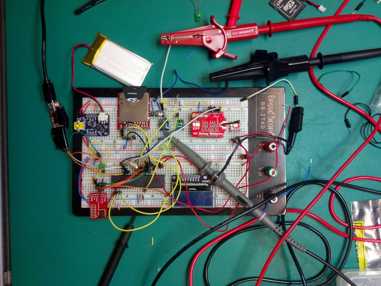
I've got just about everything soldered onto breakout boards and wired up on a breadboard:
I've been working on the code to interface with everything, and so far I've written a quick library for the tilt sensor, and I've forked Jeelab's
RTClib and added support for the BQ32000 RTC (I've submitted a pull request
here).
Here's a closeup of the RTC wired up (on the blue breakout board):
The ugly looking thing above it is a surface mount super capacitor I soldered some 0.1" headers onto to use it with the breadboard. the trickle charger is working great; it's 10:24PM now and the cap is charged up to 2.7V. I'll leave it running off the cap overnight and measure it again in the morning...
In theory, if the cap were charged to 3.3V, based on the RTC's 1.5uA maximum current draw when running on backup power, it should be 3.2 days before the cap discharges to the minimum backup supply of 1.4V. That's ignoring the cap's leakage current. From the 2.7V measured at 10:24PM, it should last 2.2 days, again ignoring leakage.
Feb 28
Hmm, at 10:18AM the super capacitor is down to 1.69V, which in ideal conditions should take about 1.7 days. It would seem that there is a lot of leakage current (the cap I'm using has no leakage current rating). I guess I'll have to look for a better cap.
Mar 3
So I've been working on the code, and it's looking like I'm going to have to run as fast as possible, meaning I should be running off a 16MHz crystal instead of 8MHz, and that means running the MCU off 5V. I'm working now on a prototype schematic; I'll probably just use a DC boost to get the LiPo to 5V, then a regulator of some sort to get 3.3V for the SD card and radio instead of dealing with a buck/boost.
Mar 11
I've been having a lot trouble designing the right power supply. To run the ATmega at 5V, I would need to have both 5V and 3.3V rails (the radio, SD card and LCD can't exceed 3.3V). The combined power requirements of the 3.3V devices means the supply would need to be capable of sourcing up to at least 700mA (40mA max for SD, 200mA max radio TX, 450mA max LCD), which means that if I use a DC boost to go from the battery to 5V, then a regulator for the 3.3V rail, the boost IC need to be capable of sourcing that 700mA plus whatever is need for the 5V rail, which total should really be at least 1A. That means two relatively hefty PMICs, plus all the required level shifting circuitry, which makes for a lot more complexity than I was hoping for.
In parallel to trying to design that power supply, I've been working on a WiFly library for the Propeller. At this point I'm really leaning towards switching to the Propeller. It would create more software complexity (namely there's still a lot I need to learn about the SPIN language), but it really simplifies the hardware design, as it runs at 3.3V with clock speeds up to 80MHz. I'm thinking one cog dedicated to the SD card, one for the WiFly serial port, one for the web event loop, and one for the LCD and UI buttons.
Here's the very beginnings of my WiFly SPIN library:
Jim: We ordered some of these parts for the CS lab in class.
Mar 19
I realized I have no real need for a graphics LCD, as all I need to display is a simple menu system. I decided to switch to the
NHD-C0216AZ-FSW-GBW, which is a very small 2x16 character display. It is much easier to use, and requires far less power.
Apr 4
Oops, turns out that LCD requires 5V, so instead I'm using the
NHD-C0216CIZ, which runs at 3.3V. It also uses an I2C interface, which is great because it requires less pins than the parallel interface the other uses.
April 8
I might switch displays yet again to the
NHD-C0216CZ. It's a pretty similar display, just with a slightly smaller form factor and SPI instead of I2C.
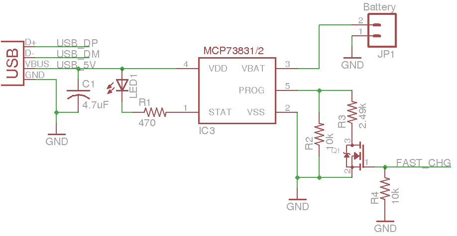
I set up my charging circuit on a breadboard to run some tests. The circuit is essentially straight out of the
MCP73831T datasheet, with the addition of a MOSFET to switch between 100mA current limit and 500mA fast-charge current limit:
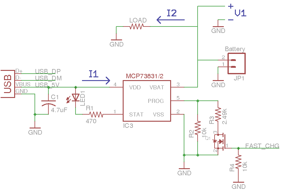
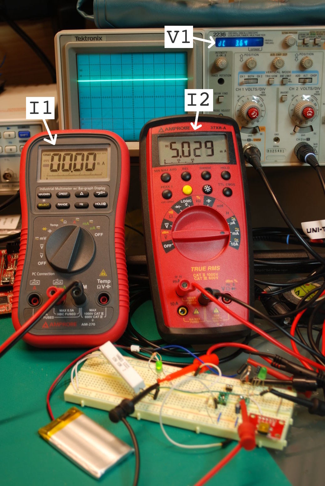
I monitored the current from the USB 5V rail into the MCP73831, the current out of the battery, and the voltage across the battery while I tried different combinations of loads and charge rates:
Without USB connected and a battery voltage of 3.64V, a load of an LED with around a 2V forward voltage and 330 ohm series resistor draws the expected 5mA from the battery:
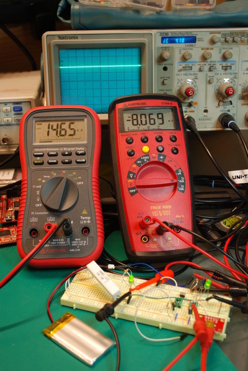
After plugging in the USB cord, the charger enters its constant voltage mode at around 4.2V (if the battery voltage was lower it would enter its constant current mode), sourcing 14.64mA to the whole system, which powers the LED while charging the battery at just over 8mA:
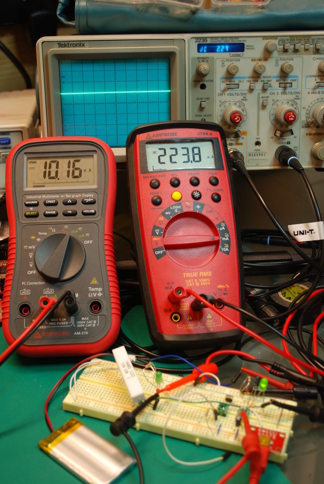
With the USB unplugged and a 10ohm load, the battery is unable to source 400mA, and the voltage drops until it reaches about 2.3 volts to supply 230mA:
With the USB plugged in and the same 10ohn load, the voltage remains at 2.3V and the charger only supplies just over 10mA:
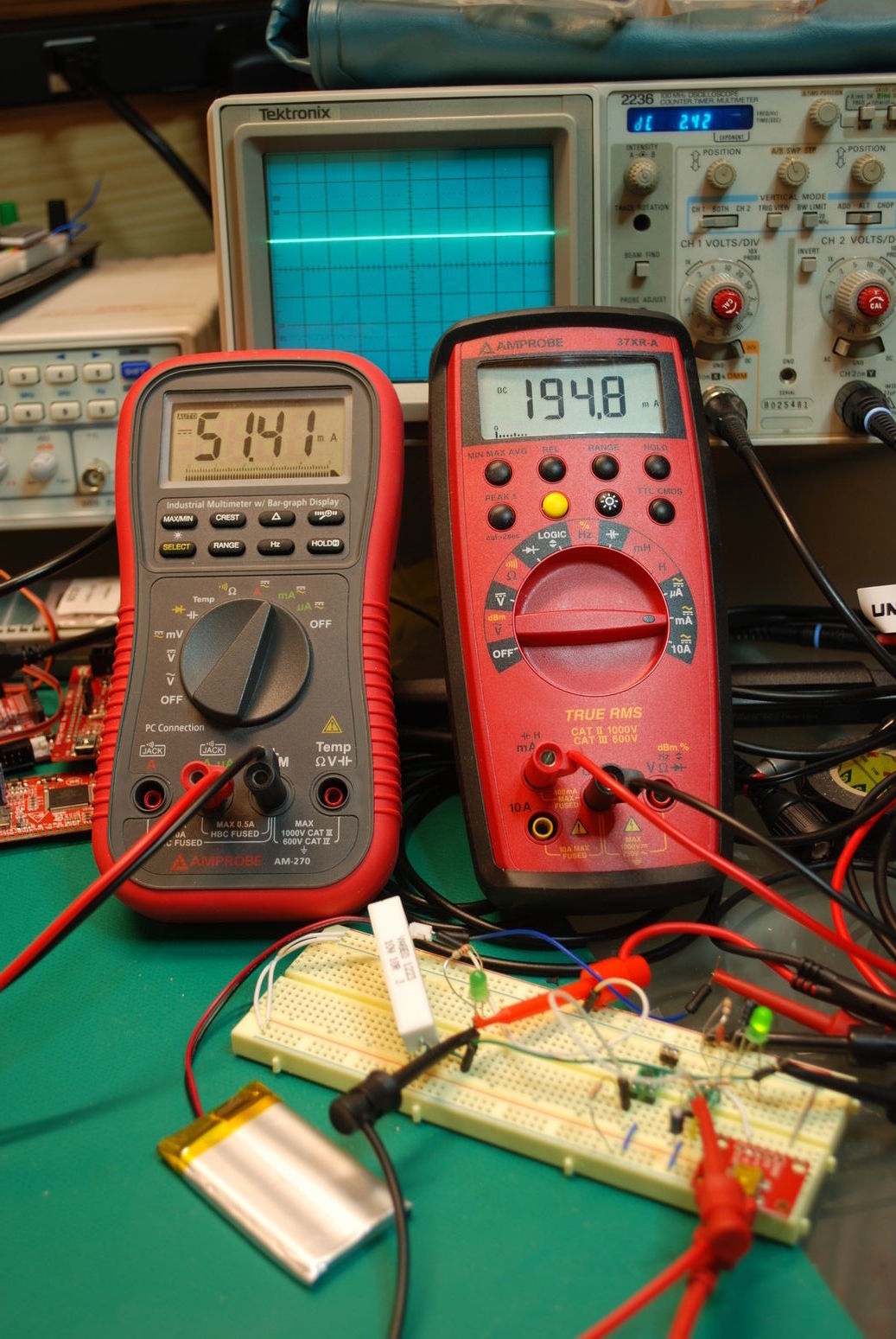
With the same setup and the charger's current limit set to 500mA instead of 100mA, the battery voltage goes up to 2.4V and the current to 51mA:
I'm not quite sure what's going on with the 10ohm load, the charger doesn't seem to be in either its constant current or constant voltage mode. The battery claims to be able to source up to 2C, where C is its capacity/h, in this case 2.6A
datasheet.
4/11
I decided to vastly simplify my power supply design and just use a 3.3V low dropout linear regulator. This means I slightly shorter working battery life, but I thinks it's well worth how much simpler the design is.
4/23
I ordered the final revision 1 boards on the 15th. By the time I had everything I needed connected to the propeller, including the number of pins I wanted on the expansion header, I had no pins left for sensors. So instead I designed a second module to plug in the back of the board which has a temperature sensor, humidity sensor, a piezo buzzer and screw terminals for the remaining pins. Design files for both are
here.