
|
Alex Hiam - Fall 2011 Designing and Building a Custom Handheld Embedded Device |
|
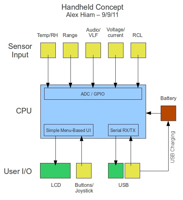
The end goal of this tutorial will be a custom built handheld digital tool
consisting of a variety of sensors (e.g. temperature, humidity, voltage,
ultrasonic range, accelerometer, etc.), some sort of user input (i.e.
buttons or a joystick of some sort), and an LCD screen for easy display of
data. The real focus of this tutorial will not be on the end result, but rather the process that is required to accomplish it. I will work my way up from studying datasheets and selecting parts, to prototyping hardware on breadboard and writing software libraries for communicating with peripherals, to drafting schematics and designing the PCB layout, to the final fabrication of the board and soldering of components. I will clearly document my entire design and fabrication process. |
|
|
End Result:
Well, looking at that proposal now, I realize how overly ambitious a plan that was. This turned out to be a good thing though, as I was forced to practice simplification, which is a step I usually try to skip. The largest simplification I made was to the power supply. I was originally under the impression that I would need a well regulated supply, and possibly even a split of 5v and 3.3v (see notes and updates links below). I had all sorts of big plans, with crazy combinations of regulators and buck/boost chips, not to mention momentary digital power switches and multiple charging sources. Power supplies were, in fact, something I always over-thought. Once I realized what a pipe dream it was to want all these things on a home-etched and hand-soldered board, I set out to simplify the design. I discovered a few things that ended up vastly reducing my bill of materials, the biggest of which was the fact that a fully charged lithium-polymer battery (upwards of near 4.2v I believe) is, in fact, within the tolerance of the majority of 3.3v devices I use, including the ST7565 GLCD from Adafruit Indestries (see Resources page)(Also, don't trust this as a rule of thumb; always consult the datasheet!). Well that's fine and dandy, but with an unregulated power supply how will I accurately convert ADC values to voltages, you ask? Well the other thing I got some practice with was using voltage dividers to bring voltages to within the 0-1.1v range of the Atmel AVR's internal analog reference generator. Of course there is a loss of accuracy from the resistors (don't use higher tolerance resistors), but I'd say it beats complicated and tiny buck/boost regulators. The most major accomplishment of the project was an Arduino library for creating snazzy menu-based user interfaces that I wrote on top of the Adafruit ST7565 library. (Can be downloaded here for the time being: ST7565_Menu). I put quite a bit of time into debugging/fussing with it, and was able to get it to a very stable state. As said Arduino library implies, I ended up using the Arduino environment in the end. I was trying to stay true to the pure AVR C code, but it just ended up being too much to deal with. Once I switched to Arduino, I was able to get a complete prototype together and running without many snags. Prototype on the breadboard: 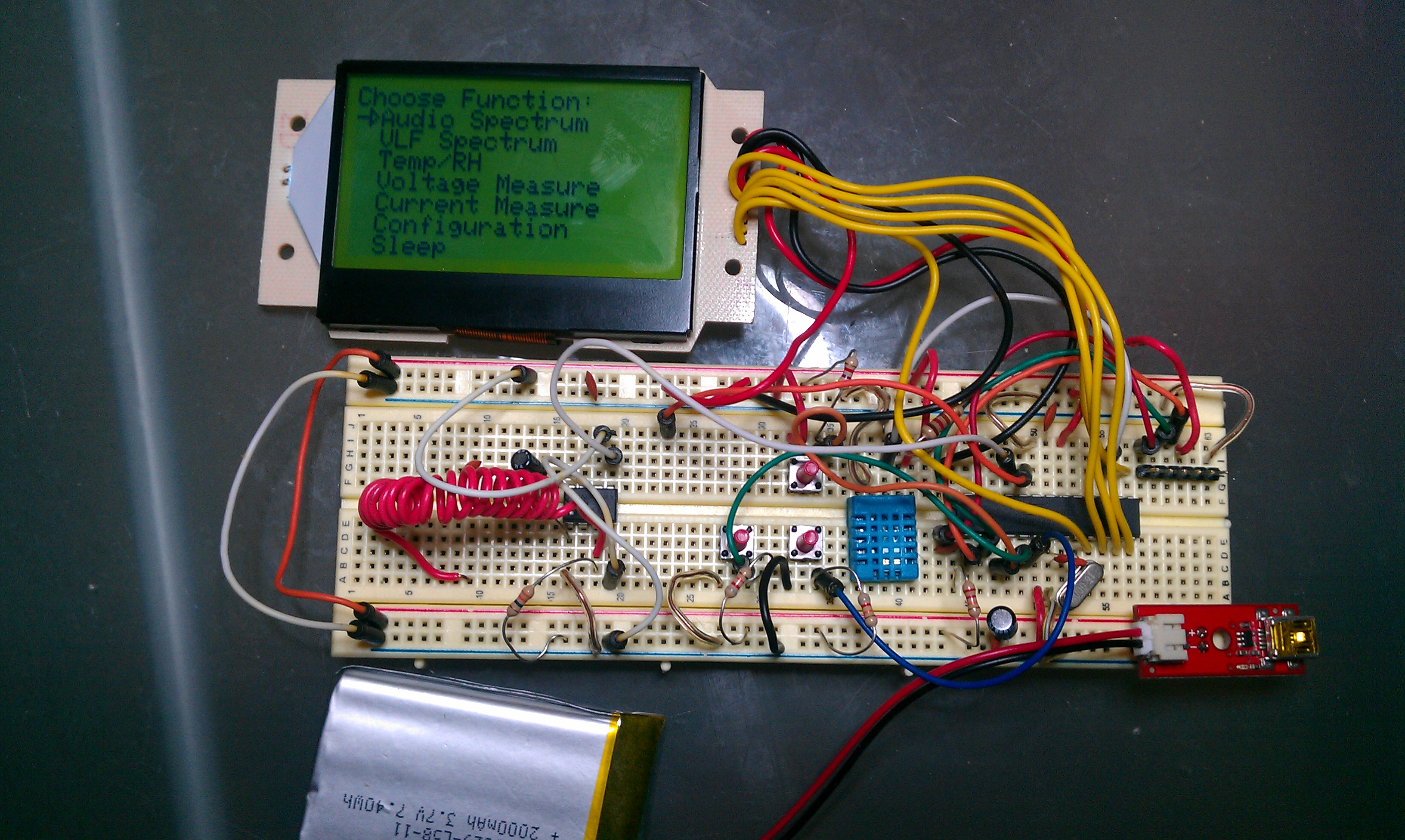
That's when I started to feel the limitations of the ATmega328's RAM. I got to the point where adding one more line of code would stop the chip completely. I started looking into the Sanguino, which is, more or less, just the Arduino bootloader modified to fit on the much larger ATmega644. For lack of time, though, I ended up downsizing my device even further (which by this time I had dubbed the 'ArduSense') and sticking with the 328. With the end of the semester rapidly approaching, I modified my end goal to completing a 'proof of concept' device (Which I sometimes call the even worse name of 'ArduSense Light'). What I ended up with was an ATmega328 with the Arduino bootloader, the ST7565 GLCD, the DHT11 temp/relative humidity sensor, and a coil of wire into a two-stage LM358-based audio amplifier, with a single-stage R-C low pass filter with a cut-off of about 120Hz or so, with which the ArduSense can measure the strength of 60Hz electrostatic fields surrounding power lines, outlets, etc.. It was a tight squeeze onto the MCU, so I didn't even bother performing an FFT on the VLF signal, but instead just took an average amplitude over time and displayed it as a graphic strength meter. So in the end I didn't have the snazzy custom-etched beauty of an everything-sensor I had unrealistically hoped for, but I do have one ugly, perf-board monstrosity of a proof of concept that works perfectly; a fine compromise if you ask me. Here's a video of the final proof of concept:
And the Arduino sketch:
Oh, and for a battery charger I'm just using this right now:
And their 2000mAh li-poly:
The final schematics are on the schematics page linked below.
Grading
|
Pages:
|