Making the ATtiny85 do interesting things
Acknowledgements
First and foremost, very little to none of my learning of how this chip works would be possible without the much needed help of Alex Hiam (
https://github.com/alexanderhiam).
In addition, much thanks should go to my Plan sponsors Jim Mahoney and Tim Segar for their continued support and reiterations of things I did not understand.
Purpose
This series of pages is my effort to document the process of figuring out how the ATtiny85 works so that it would be easier for someone else to figure out in the future. I found it really hard to find information on really basic examples so this is my answer.
This is structured in such a way that each page introduces a new topic or tool. This should work in a roughly modular way.
When my own knowledge is deemed fuzzy and someone else has explained something already, I will link to their better and/or more exhaustive explanation.
Table of Contents
Setup
- introduction:
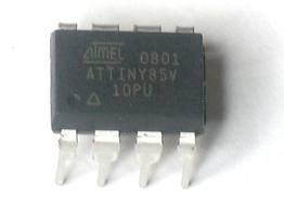
- What's a microcontroller? Why the ATtiny?
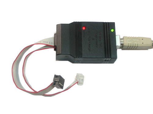
- hardware:
- The bare minimum of hardware and materials needed to program a chip.
- adapter:
- covers the creation of a proto-board 6-pin programming header to 8-DIP adapter.
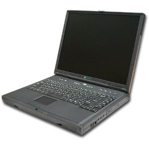
- software:
- Libraries, packages and files needed.
- datasheet:
- registers:
- Registers (in the context of the ATtiny85) explained along with a brief introduction to binary arithmetic.
Inputs and Outputs, a How-To
- blink:
- An LED blinks. The most basic of outputs.
- switch:
- A switch controls whether an LED blinks or not. The most basic of inputs.
- knob:
- Introduction to the the Analog to Digital Converter.
- A basic analog input with a potentiometer.
- An LDR is swapped out for the potentiometer.
- things:
- an ongoing list of things I've made and an acknowledgements/bibliography section.
Next:
A brief explanation of what a microcontroller does and why this whole document exists (continued).
![[paper clip]](/courses/source/wiki_images/paper_clip_tilt.png)